

Building this tiny home trailer has thrown up a lot of problems, most of them caused by deciding to custom build almost every single part ourselves but week we moved on to what is effectively version three of Pete’s independent suspension design. And we got to tackle a very practical question: how do you shift a nine‑metre‑long trailer that’s wedged the wrong way round in the workshop, using just human power and some new hardware on the front end?
The custom independent suspension has now reached what Pete would prefer to call version 2.5. The original layout in CAD looked fine, but in reality there wasn’t enough travel before the arms and wheels would end up fighting the habitat floor, and we’re determined not to lose any living space to wheel arches.
Because all of the brackets were height-adjustable and bolted to the chassis from the start, we could move it all up a hole to tweak the arm angle and raise the mounting height. That small change gave us a lot more usable travel, a bit more ground clearance and a better coupling height at the front of the trailer. Once everything was fully welded and bolted, there was no detectable play in the system – the truss design on the arms is doing its job.
Earlier in the build we tried to save a bit of money on the airbags and ordered a cheaper pair online, only to discover they used an obscure thread and the listing wasn’t quite what it claimed. They went back, and the search shifted to proper commercial‑grade bags that would still sit nicely in our existing bracket layout.
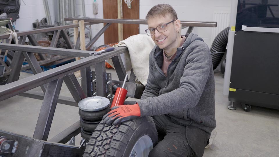
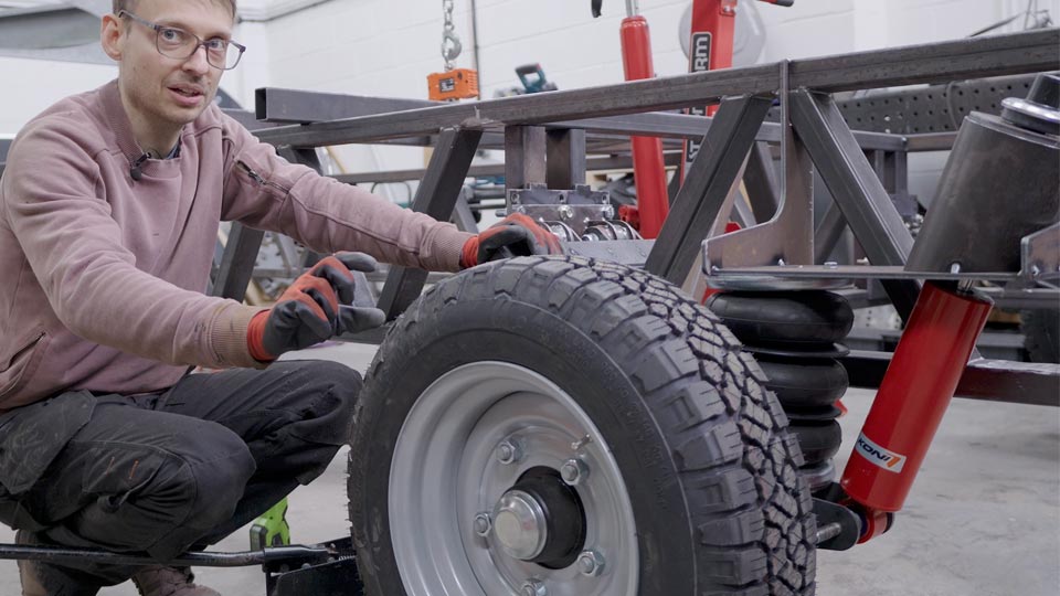
Those upgraded airbags are now fitted. They’re physically larger and have a much wider working range, which makes it easier to adjust ride height for both ground clearance and coupling without running them at the extremes of their travel. At the correct pressure the bags sit close to their spec‑sheet ride height, and the shock sits roughly mid‑stroke with room to move both up and down.
Choosing a shock absorber has been its own design problem. The unit needs to live in a tight space and still cope with roughly a tonne of loading on each corner. We’ve settled on a compact but much more substantial Koni shock, mounted on a custom bracket so that it runs at an angle based on the tangent of the arm’s arc. That way, the shock is simply compressing and extending, rather than trying to twist as the suspension moves.
With everything assembled and the jack under the hub, we cycled the suspension through its travel. From ride height we now have around 150 mm of upward movement and about 100 mm of droop, while keeping roughly 400 mm of ground clearance under the chassis rail. Even when the jack maxed out, the wheel was still in contact with the floor, which shows just how much movement is now available.
The lightly built, skeletal chassis has made it tricky to find strong, well‑supported mounting points for the top of the airbag and shock without simply welding on huge plates. After a lot of sketching and a long chat with Pete’s dad, the solution ended up looking a bit like something off a tank.
We’ve added a large diameter tube with a capped plate on top that the shock bolts into. Inside that cap, the threaded top of the shock sits between two rubber bushings, with an oversize hole in the plate so the rod can move slightly without binding. The rubber provides just enough flex for the assembly to act as a pivot while still holding the shock in line with the forces it needs to resist.
Structurally, that tube ties the mount into both the top and bottom of the chassis, so loads from the shock are carried into the frame in the right direction rather than twisting one thin section. As a bonus, it acts as a little housing that keeps muck, road spray and weather off the top of the shock hardware.
To make working around the airbags easier, we’ve also fitted small bicycle‑style valves temporarily into each bag. That lets us vent them quickly, compress them out of the way while we fit brackets and then refill them once the hardware is in place.
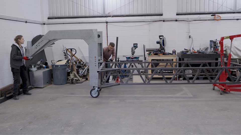
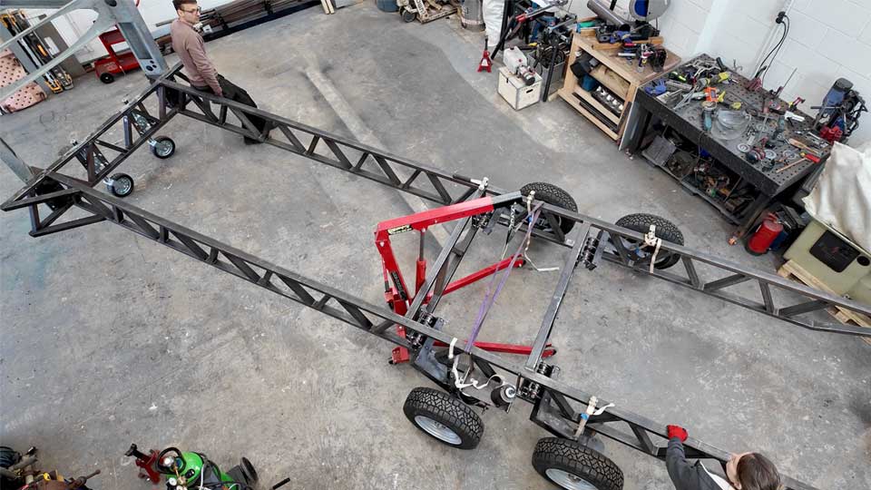
The trailer ended up being built exactly where we now need open space for laying up fibreglass on the shell and floor, which meant one unavoidable job: work out how to move a nine‑metre trailer frame around the workshop by hand.
We decided to add a pair of heavy‑duty jockey wheels to the front of the chassis. These are similar to the wheel you’d find on the front of a caravan but scaled up and rated to around 900 kg each. Mounting one on each side spreads the load, gives a much more stable footprint and keeps the turning circle nice and tight indoors.
Each jockey wheel bolts to a custom bracket made from flat bar that is welded to the front crossmember on the chassis. One diagonal brace on the crossmember interfered with a bolt hole, so three of the mounting points use conventional bolts and the fourth is a tapped hole through an 11 mm stack of plate. That solution is more than strong enough because these wheels will only ever see slow‑speed manoeuvring in the workshop and maybe a car park or campsite one day.
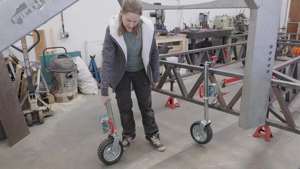
A key detail on these units is their party trick: once the trailer is sitting on its main suspension and tow vehicle, each jockey wheel can be released, swung up and locked against the chassis. That keeps them clear of the ground and protects the overall ground clearance, instead of leaving a wheel hanging down and ready to catch on rough tracks.
In their standard form, the cranked handles at the top of the wheels would hit the bodywork once the shell is in place. For now, we’ve removed the handles and experimented with using a drill to raise and lower the legs, and there’s scope in future to add a simple motorised drive if we want to make them powered.
When we first took the weight on the jockey wheels, the front of the trailer came in at around 300 kg in its current incomplete state, which gives a useful early data point for future weight calculations.
With the front supported on jockey wheels and the suspension working at the back, we moved on to the slow process of actually shifting the trailer. Using the engine crane at the rear, we lifted the back of the frame off its stands, then inched the trailer sideways and forwards around the old axle, walls and machinery.
Each move involved nudging the crane, steering the jockey wheels, readjusting the crane, nudging a bit more and reassessing. It was a combination of lifting, rotating and rolling that took time but kept everything under control. After 20 gruelling minutes, the trailer was parked where it needs to be for the next phase of work, and the centre of the workshop is now clear again with space for activities!
We officially weighed the bare chassis by lifting all four corners with straps on the engine crane, watching the digital scale climb as we adjusted the pick‑up points to find the balance. The final reading was around 650 kg with all corners just clear of their stands. One extra crossmember on its own came in at roughly 20 kg, and the fifth‑wheel tow ball weighed about 5.5 kg, despite feeling much heavier in the hand.
That first weigh‑in gave us a useful baseline, and the plan is to keep weighing individual components – crossmembers, hitch hardware, habitat panels – as they go on, before doing a final run to a weighbridge. The latest suspension tests, with the jack running out of travel before the suspension does, and the way the chassis stays flat while one corner is lifted, are good signs that the frame is both stiff and still within the weight envelope we’re aiming for.
All of that ties back to the goal we set at the start: a strong but relatively light trailer chassis, with independent suspension and proper travel, that can safely support a tiny home habitat without wasting weight on steel that doesn’t earn its keep.
