Somewhere between the crunch of a giant cable cutter and the smell of epoxy primer, the tiny house finally got its own power system – and a little brain to keep an eye on it.
Last time, we’d just finished the utility cabinet on the gooseneck of the trailer. That aluminium box is where all the air suspension controls, hydraulic levelling legs and electrical bits are going to live, but up to now it’s mostly been an empty shell with big ambitions.
This week, we had to give it power. Click here to jump straight to the video.
The goal for this box was twofold:
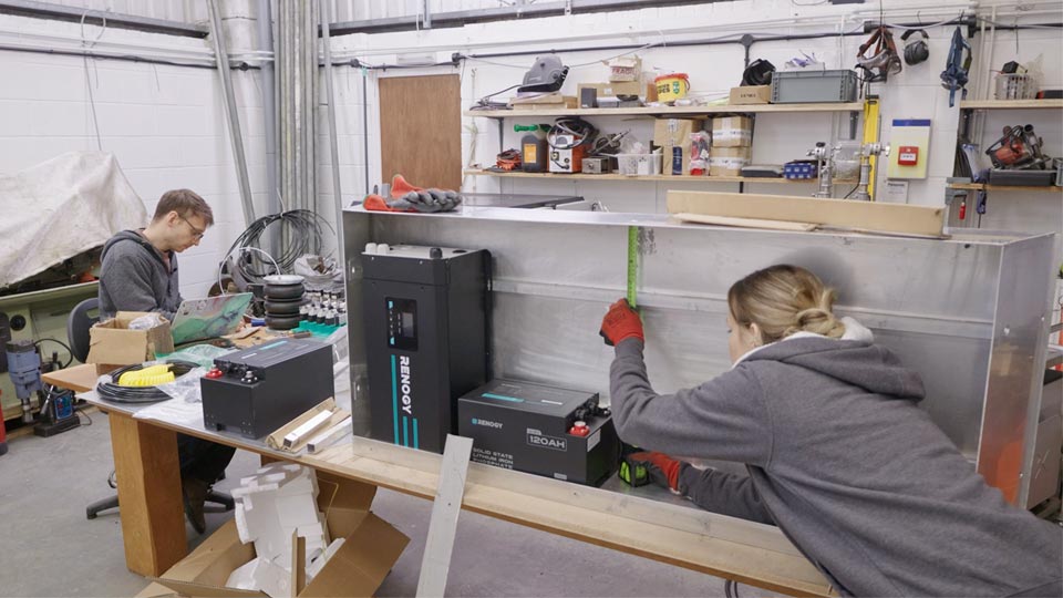
Rather than trying to build the forever system on day one, we went for a small, robust 12 V setup: two 120 Ah lithium batteries in parallel feeding a beefy inverter/charger. On paper that gives about 2880 Wh of storage, but because you never drain batteries to zero, we’re treating it as roughly 2 kWh of usable energy – plenty for tools, lights, and to bail out the house if needed.
It sounds straightforward written down.
In real life, step one was just: “where on earth does this very heavy inverter actually go?”
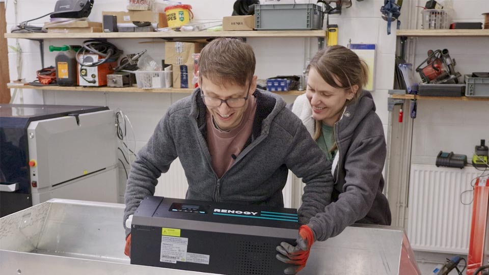
In the last episode we mocked everything up with cardboard cut‑outs and felt very pleased with ourselves. Then the real inverter arrived and we picked it up.
The original plan was to hang it off the back wall of the box, but once we felt the weight, bolting it to a vertical surface suddenly felt like a daft idea.
Instead, we flipped the whole layout and stood the inverter upright on its “butt”, supported by the base of the box, then added extra ribs across the back so we still had solid fixing points.
We only had square box section in the workshop, which would have pushed everything too far out, so Pete sliced one side off and turned it into a sort of DIY C‑channel that could sit tight to the wall and still be strong.
The end result is a solid mounting rail that keeps the inverter close in, with proper airflow gaps all around.
Because the inverter has cooling vents underneath, we cut matching holes through the floor of the box and planned a little bug‑screened vent so it can still breathe without sucking in insects.
The next problem was the batteries.
We played with a few ideas: shelves from box section, angle‑iron trays, fully welded cages. Everything either ate too much space, or didn’t use the side screw holes properly.
In the end we designed some slim laser‑cut cradles that pick up the eight screw holes on each side of each battery. They slide into the box, bolt directly to the batteries and then sit on chunky angle that acts as a shelf, with a second layer of angle welded behind for the upper battery.
It looks far more professional than the earlier sketches and wastes almost no room, but it took hours to get right: measure, model, cut, test, tweak, repeat.
We both love how it turned out though – this little cabinet is probably the strongest thing we’ve built so far.
If you watched the previous episode you’ll know we obsessed over keeping aluminium and steel apart to avoid galvanic corrosion.
Cue this episode: we immediately start installing steel rivnuts into the aluminium box so we can bolt the inverter on properly.
Aluminium rivnuts just didn’t feel strong enough for that much weight, and aluminium bolts aren’t really a thing you’d trust, so we accepted the compromise.
To help, we flooded each rivnut with a generous amount of PU sealant before squeezing it in, so there’s at least a layer of goo between the steel and the aluminium.
Once the big metal bits were in, we started tackling the invisible jobs: drainage and ventilation. Loads of you mentioned in the comments that a big sealed box on the front of a trailer will always find a way to collect water if you don’t give it an escape route.
We drilled two large drain holes in the base and I’ve been prototyping 3D‑printed grommets that pull a foam floor mat into a gentle slope towards those holes. The idea is that any condensation, spills or stray rainwater runs towards the drains, down through the grommets and out, instead of sitting under the batteries.
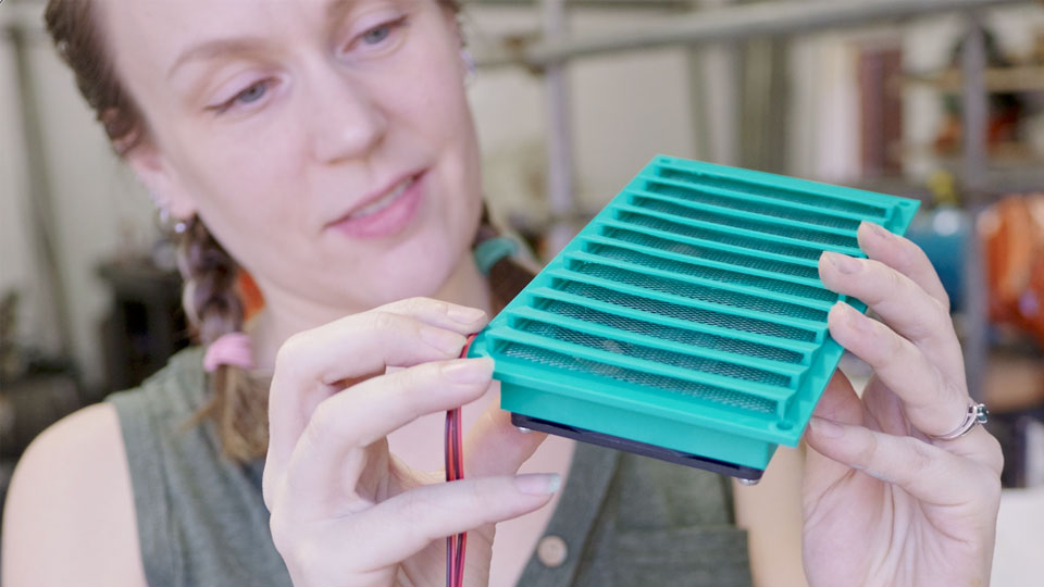
For cooling, I designed a louvred side vent with two small computer fans and an aluminium bug mesh behind it. The plan is to wire those through a thermal switch so they only wake up when the inverter starts to get toasty.
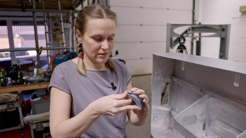
Before we buried all this behind wires, we wanted to protect the metal properly. So we pulled the neck back off the trailer, cleaned everything within an inch of its life and reached for the paint.
The primer is Jotun Jotamastic 90 Alu, a two‑component epoxy mastic with aluminium flakes that’s designed for long‑term corrosion resistance on steel, aluminium and galvanised steel, even when surface prep isn’t perfect. Over the top of that we used Jotun Hardtop AX in teal and orange, which is a two‑pack polyurethane topcoat with a glossy finish, very good gloss and colour retention, and solid chemical resistance.
Our first attempt at rolling it on was a bit of a mess. We tried to be “efficient” by letting the foam roller go almost dry between passes, which just destroyed the roller and left patchy coverage.
Lesson learned: keep the foam roller properly saturated and work quickly, and the finish goes on beautifully. After a couple of hot days the Jotamastic and Hardtop together felt almost plastic‑wrapped, like a vinyl shell over the metal.
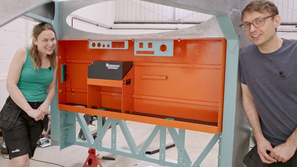
Colour‑wise, we were aiming for a kind of vintage teal and soft orange.
What we actually mixed looked more like turquoise baby blue and traffic‑cone orange.
The blue‑green is lovely; the orange, I… tolerate.
The more we hide it behind equipment, the more I like the tiny flashes that peek through.
With paint dry and mounts done, it was time for the bit that always looks glamorous in photographs and feels horrible when you’re actually doing it: big DC cabling.
We wired the two 120 Ah batteries in parallel, then ran heavy cable through a main isolator and a mega fuse before diving into the inverter. Those cables really don’t want to bend neatly, and every run fought back, but once the first properly crimped lug went on it started to feel like a real system.
On the safety side, we added:
Because the trailer isn’t permanently tied into a house earth, we bonded an earth lead to the trailer chassis and rely on the inverter’s built‑in automatic earth–neutral bonding.
The exact details for that are very system‑specific, so if you’re fitting your own, you really do need to design and check your own setup.
Once the big cables were finally in, we flipped the isolator and waited for the bang. Instead, we got a slightly grumpy beep and a very sensible display.
Our inverter is also a charger, so:
We didn’t want a chunky blue 16 A “commando” connector inside the small box, partly because it wastes space and partly because the built‑in charger only pulls around 4–5 A AC, so the cable would be total overkill.
Instead, Pete borrowed a trick from the events world and used a compact locking PowerCon‑style connector rated for 240 V at up to about 13 A. It clicks in, seals nicely and takes up far less room, while still being specced correctly for the load.
On the outside end of that lead we just fitted a standard 13 A UK plug, but it could just as easily be one of the blue campsite plugs or something else, depending on what we’re plugging into.
We did a few gentle tests: first a small battery charger, then a powerful filming light, watching the inverter report around 70 W and then roughly 225 W of output. We resisted the urge to go straight to “angle grinder at full send”, but that day will come.
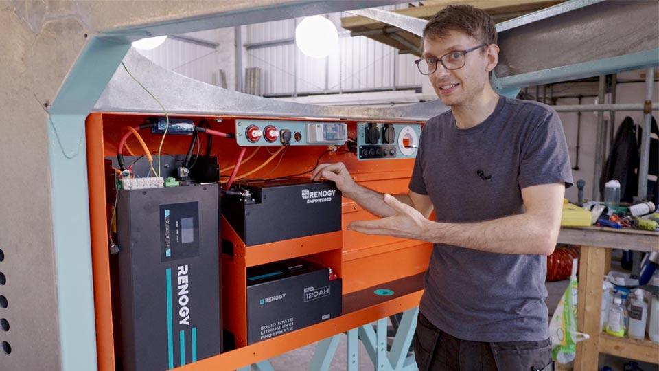
All the main components in this system are from Renogy: the lithium batteries, the inverter/charger, the DC‑DC charger and the Renogy One Core hub.
The batteries have their own smart battery management systems and talk over Bluetooth and other common protocols like CAN bus. The Renogy One Core acts as a central hub, pulls that data together and shows us state of charge, usage, and what’s going in or out – plus links into the app so we can check it from our phones.
We had to tweak exactly two settings on the inverter: battery type to lithium, and frequency to 50 Hz instead of the default 60 Hz. After that, the whole ecosystem really was close to plug‑and‑play.
Next, we’ll be fitting the 50 A DC‑DC charger that can accept both alternator input and solar.
That means:
With roughly 240 Ah at 12 V, a full charge from empty using just the DC‑DC charger would take around four hours of driving, which is totally realistic between campsites. Most of the time it will just top things up in the background so the bank stays healthy.
So: Moose is now the tow vehicle and the rolling generator, and the tiny house carries its own independent power system that can be charged on the move.
The nicest part of this whole saga is knowing that this isn’t just a one‑trick pony for the trailer hardware.
Because we’ve built it as a self‑contained 12 V and 230 V system with its own monitoring, we can also treat it as a backup generator for the tiny house once the main system is wired.
If the primary power system in the house ever needs work, or if we want extra resilience in winter, we can just plug the house into the trailer, flip a few switches and let the utility box keep the lights on.
It’s a small step on the road to being properly off grid, but a big one for us: this is the first time something on this project feels like a finished, integrated system rather than just a part waiting for its friends.
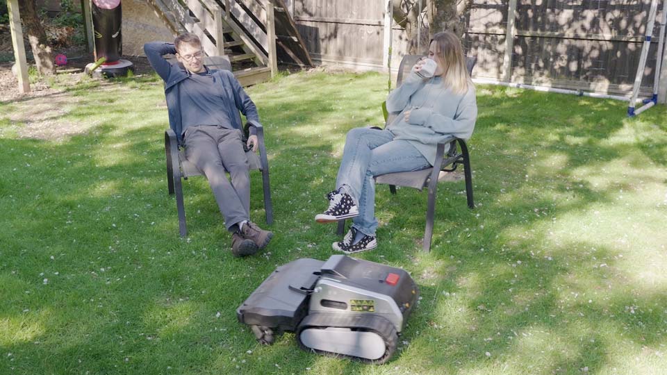
For this episode we teamed up with LYMOW, who sent over their One Plus robotic mower for us to try.
It’s a tracked little tank with dual rotary SK5 steel blades spinning at up to 6000 rpm, plus a cyclone airflow system that lifts the grass before it cuts, so you get a really even finish and fine mulch instead of big clumps. It maps the garden with RTK‑VSLAM, handles slopes and lumpy ground far better than the usual tiny wheel‑mowers, and once you’ve driven it round the boundary with the app it more or less gets on with it by itself.
If you fancy handing lawn duty over to a robot so you can spend more time tinkering with your own off‑grid projects, you can check out the LYMOW One Plus here: https://dada.link/vw63es
We’ve also decided to give ours away. If you’d like a chance to win the exact mower you see in the video, we’re running a little raffle over on our site:
🎟️ Enter the raffle here: raffle.roadtooffgrid.com
As always, using those links helps support the channel at no extra cost to you, and means we can keep going with all our hair-brained shenanigans.