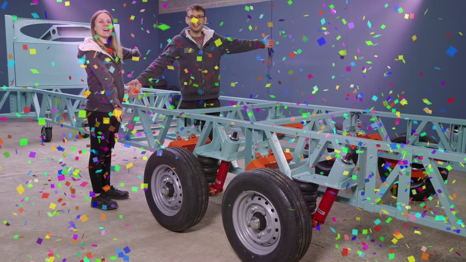
Last time, Pete cut the hydraulic leg brackets clean off the chassis with barely an explanation. We know what some of you were thinking: here we go, Pete’s changing his mind again. This time we’re explaining ourselves properly, finishing a week of painting with the world’s smallest paintbrush, and finally bolting the suspension on for good.
If you would rather watch than read, jump straight to the video.
The hydraulic levelling legs looked brilliant. They came out at an angle like the stabiliser legs on a digger, Pete had done the maths and they were crazy strong. We fully stand behind it as an idea. The trouble is we only built that system because we had the parts left over from the first set of levelling legs we made for Moose, back when he was going to be a camper.
Once we actually weighed it up, it was massive overkill. The whole hydraulic pack weighed around 200kg, and it added an entire extra system we’d need to maintain, including access for hose leaks. It also couldn’t give us proper self-levelling or any of the smart features we wanted, because you don’t know the exact position of a hydraulic ram without bolting on extra sensors. So we took the weight back and are going electric instead.
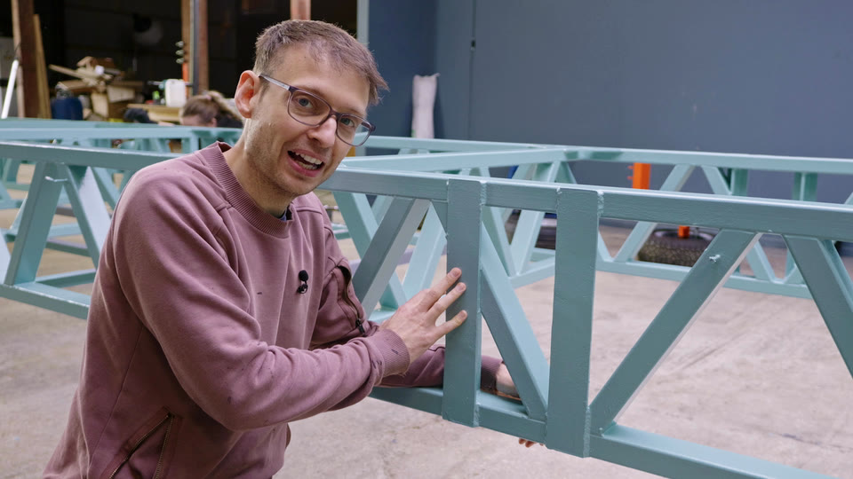
The new plan is electronic linear actuators, specced strong for pushing straight down and mounting to the side of the chassis without poking above or below the rail. Space is tight, so Pete’s custom-designing our own brackets rather than buying something off the shelf.
There’s one catch: our ground clearance is greater than the reach of the actuator, so even fully extended, the feet won’t reach the floor. The fix is simple. We’re making leg extensions that screw onto the bottom of the ram, with the foot on the end. When we’re parked up, we’ll pull the extender out of the side storage, screw it on, and level up using the full 160mm stroke of the ram.
The real win is inside the actuators. We’ve specced them with Hall effect sensors, so the system will know exactly how far each leg has extended or retracted, when it’s hit the end of its travel, and how much load is on it. That means self-levelling at the touch of a button. Pete’s been learning CAN bus so all of this, plus air pressure sensors in the airbags, can talk to each other and eventually to one trailer utility app. Oh, the possibilities!
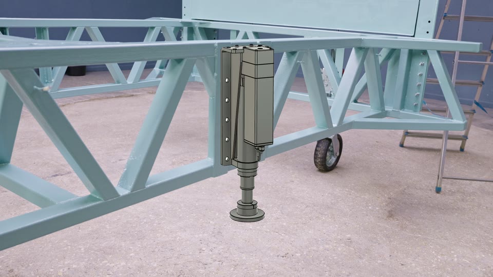
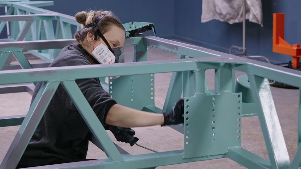
While all that was being specced out, I spent the best part of a week painting the suspension swing arms and the full 9 metre trailer chassis. Spraying would have been quicker, but it would have meant building a proper spray booth, buying a better gun, and losing around two thirds of our paint to overspray on thin box section. So it was rollers for the big faces and a tiny brush for every fiddly corner we’d designed into those shapes ourselves. The chassis truss design is strong and brilliant for everything else. Painting it is another matter entirely.
Partway through all this, our workshop roof started leaking properly, and we got word the roofers were coming the next morning to strip out the gutters and a row of sheets on both sides. That meant a sudden scramble to get the wheels back on, move the trailer, and clear everything out from the middle of the workshop so a scissor lift could get in. We weren’t able to be on site for the three or four days the work took, which is why this update ended up running a week late.
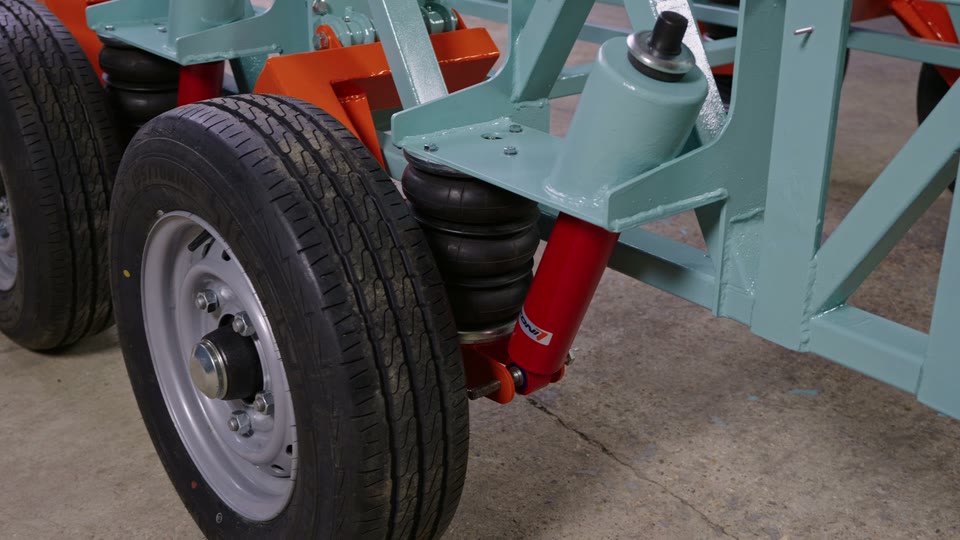
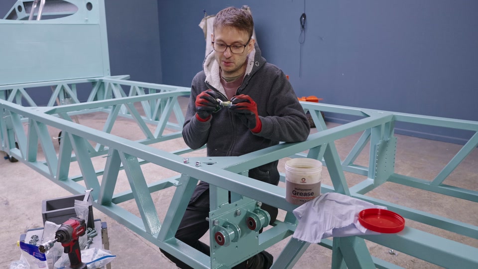
It was time to bolt the suspension arms on properly for the last time. These house the polyurethane bushings each arm pivots on, with an array of bolting points so we can adjust the suspension geometry or ride height later if we ever need to. This time it’s greased nuts and bolts with nylon locking nuts, because we’re committed.
To check the geometry, we used the forklift to raise and lower the trailer and watch the arm travel through its full arc. We were checking whether a triangular gusset on the arm, which stiffens the whole thing, would ever catch the edge of the chassis rail at full extension. It didn’t. At full droop the arm was simply hanging off the shock absorber, which is currently acting as the overextension stop. We’ll likely add a strap as extra insurance, though realistically the suspension should almost never sit in that position.
For bump stops at the other end of the travel, the plan is a rubber puck that sits around the shock and compresses up against the top mount, a common and simple way of doing it. Watching the full range of travel confirmed what Pete designed on paper: ride height sits roughly halfway through the shock’s stroke, giving equal travel up and down.
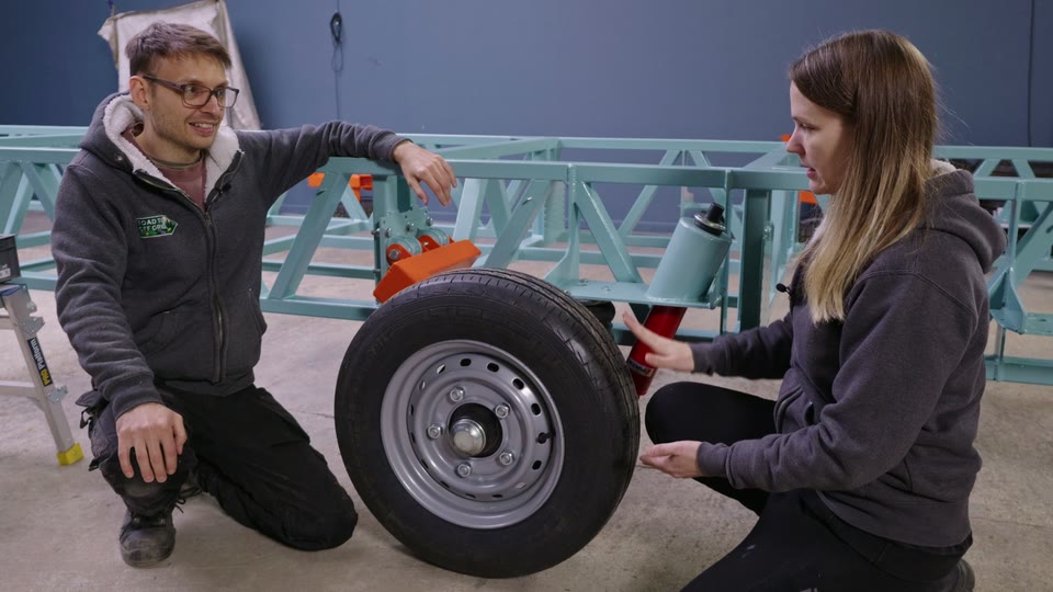
With the new wheels on and the orange suspension accent peeking through, it finally looks the part. We can’t road test it properly until the habitat shell is built, since it’ll need to go through Individual Vehicle Approval (IVA) once the trailer is complete, but it’s a brilliant place to be heading into that build from.
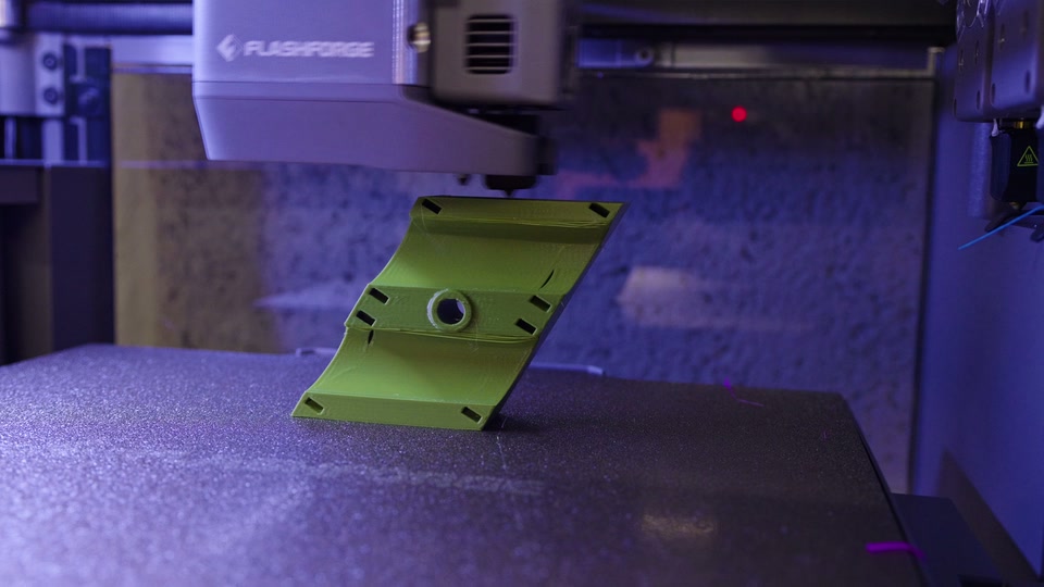
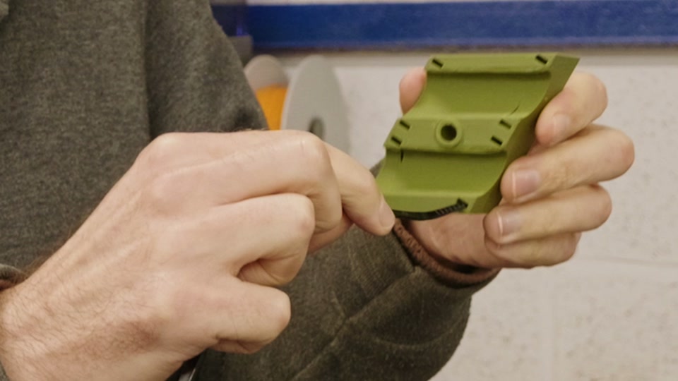
Alongside the suspension, Pete’s been prototyping a bracket to carry the wiring loom and air lines along the chassis, wrapping it around the rail at a single bolting point so it can’t rotate. We went through a couple of design iterations on our new Flashforge 3D printer, including a version with channels for zip ties to clamp the cables in place.
The early prototypes were printed in PLA, which is great for fast, cheap iteration but deforms easily when heated, so it’s no good for the finished part. For that we’ll move to nylon, which needs to be dried out in the printer’s heated enclosure before use. Nylon is hygroscopic, meaning it absorbs moisture from the air, but rather than weakening it, that moisture actually stiffens the plastic once it’s printed, which works in our favour here. The printer can also run four filaments at once through separate tool heads, so down the line we could print a squashy TPU section straight into the cable channel to protect the wires, no separate sleeve needed.
With the hydraulic pack gone, the utility cupboard gets a rethink. Our two 12V batteries will be wired in series instead of parallel, giving us a 24V system that lets us run much smaller cable sizes. We’re keeping a small external inverter for a 240V backup outside the trailer, and the space freed up by removing the hydraulics will house a DIN rail control system for the levelling legs and suspension, built around a programmable logic controller Pete’s been learning from scratch.
Buying an equivalent self-levelling kit, even sourced directly from China, would have cost a few thousand pounds. Building it ourselves saves roughly £3,000, and once the old hydraulic gear is sold on, it should more or less cover itself.
Why did you switch from hydraulic to electric levelling legs?
The hydraulic system weighed around 200kg, added a whole extra system to maintain, and couldn’t easily support self-levelling. Electric actuators are lighter, self-contained, and include Hall effect sensors that track position and load.
How will the electric actuators reach the ground?
Our ground clearance is greater than the actuator’s reach, so we’re making screw-on leg extensions with feet on the end, stored in the side lockers and fitted when we park up to level.
What is CAN bus and why are you using it?
CAN bus is a communication protocol that lets sensors and systems talk to each other over a shared network. We’re using it to link the levelling legs, airbag suspension and other trailer systems together.
Why use nylon instead of PLA for the finished cable brackets?
PLA is great for quick prototypes but will quickly deform in high heat. Nylon handles heat and UV far better, and although it absorbs moisture from the air, that actually stiffens the finished part rather than weakening it.
Why run a 24V system instead of 12V?
Wiring the two batteries in series instead of parallel gives us 24V, which lets us use significantly smaller, lighter cabling throughout the trailer.
Flashforge sent us their Creator 5 Pro, and it’s already earning its keep. It’s what Pete has been prototyping the chassis cable brackets on this week, and he’s been having a lot of fun with it.
What sold us is the four separate toolheads. Most multi-colour printers push everything through one nozzle and have to purge the old filament every time they switch, so you end up with little piles of wasted plastic. The Creator 5 Pro just picks up a different head, with four colours or four completely different materials ready to go. That means we can print our final brackets in nylon with a squishy TPU lining in the cable grooves, all in one go, so the wires are protected without a separate sleeve.
It’s built for proper engineering plastics like nylon, ABS and ASA too, with a heated enclosure, built-in HEPA filters and a chamber that doubles as an oven to dry out nylon before printing. For the price, it’s a seriously capable machine.
Use code C5CREATOR30 for an extra £/$/€30 off the discounted price on the official website:
🇬🇧 UK store
🇪🇺 EU store
🇺🇸 US store
🇦🇺 AU store
Thanks for supporting the brands that support the build! 💚